swarm のスケールを試す
ここで扱う例は、 Swarm クラスタ上に投票アプリケーションをデプロイします。例の流れは Swarm クラスタを作り、クラスタ上にアプリケーションをデプロイします。典型的なデプロイ手順例として説明するのを意図しているため、この流れを通します。
投票アプリケーションの構築と手動でデプロイした後、Docker Compose ファイルを作成します。あなた(もしくは誰か)はこのファイルを使い、アプリケーションの更なるデプロイやスケールが可能になります。
例について
あなたの会社はペットフード会社です。スーパーボウルのコマーシャル枠を購入します! コマーシャルでは、視聴者に対して調査のために犬か猫かの投票を呼びかけます。この調査は100万人もの人々が投票してもウェブサイトが止まらないようにする必要があります。結果をリアルタイムで知る必要はなく、結果は会社のプレスリリースで公開します。しかし、どれだけ投票されたかは、投票後とに確実に把握する必要があります。
この例では Amazon Web Services (AWS) 上で動く Docker Swarm クラスタに、アプリケーションをデプロイします。AWS は単なる例です。このアプリケーションにとって必須ではなく、デプロイのために使うだけです。Docker swarm クラスタ上にアプリケーションを展開するには、Microsoft Azure のような他のクラウド・プロバイダや、物理データセンタ上のオンプレミスや、あるいは、自分のノート PC 上の開発環境でも構いません。
この例では以下のハイレベルなステップを進めていきます。
- deploy-your-infrastructure
- create-the-swarm-cluster
- overlay-a-container-network-on-the-cluster
- deploy-the-voting-application
- test-the-application
例を動かす前に、アプリケーションと Swarm クラスタのアーキテクチャを理解していきます。
アプリケーションのアーキテクチャ
投票アプリケーションは Docker 化されたマイクロサービス・アプリケーションです。並列なウェブ・フロントエンドを使い、ジョブを非同期のバックグラウンド・ワーカに送ります。アプリケーションは任意に大きくスケール可能な設計です。次の図はアプリケーションのハイレベルなアーキテクチャです。
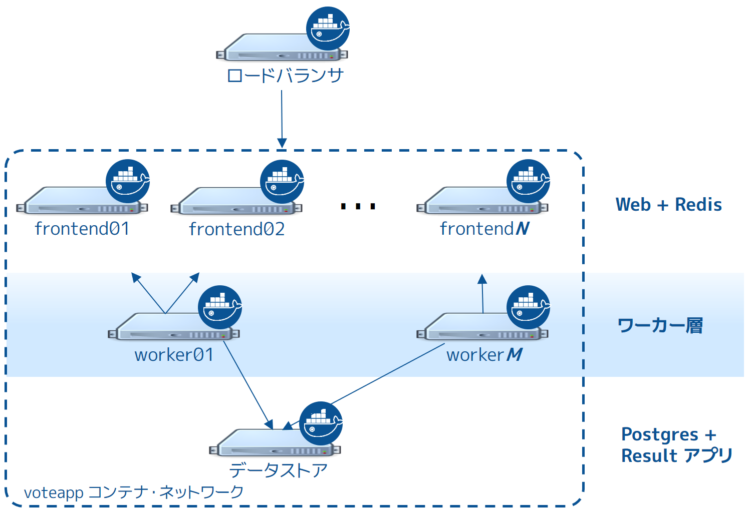
このアプリケーションは完全に Docker 化(Dockerized)しており、全てのサービスをコンテナ内で実行します。
フロントエンドは interlock ロード・バランサと n 台のフロントエンド・ウェブサーバで構成され、クエリを作成します。ロードバランサは任意の数のウェブ・コンテナを背後で扱えます( frontend01 ~ frontendN )。Webコンテナはシンプルな Python Flask アプリケーションです。各コンテナは投票を受け付け、同じノード上の Redis コンテナにキューを渡します。各ウェブ・コンテナと Redis キューのペアは独立して処理されます。
このペアはロードバランサと個別に連係できます。そのため、アプリケーション全体を需要に応じて任意の大きさにスケール可能です。
フロントエンドの背後にはワーカ層があり、別々のノードが動いています。この層は、
- Redis コンテナをスキャン
- 投票のキューを回収
- 重複投票を防ぐために投票結果を複製
- 別のノードにある PostgreSQL が動いているコンテナに結果をコミットする
Swarm Cluster Architecture
To support the application the design calls for a Swarm cluster that with a single Swarm manager and 4 nodes as shown below.
All four nodes in the cluster are running the Docker daemon, as is the Swarm manager and the Interlock load balancer. The Swarm manager exists on a Docker host that is not part of the cluster and is considered out of band for the application. The Interlock load balancer could be placed inside of the cluster, but for this demonstration it is not.
The diagram below shows the application architecture overlayed on top of the Swarm cluster architecture. After completing the example and deploying your application, this is what your environment should look like.
As the previous diagram shows, each node in the cluster runs the following containers:
- frontend01:
- Container: Pyhton flask web app (frontend01) Container: Redis (redis01)
- frontend02:
- Container: Python flask web app (frontend02) Container: Redis (redis02)
worker01: vote worker app (worker01) store:
Container: Postgres (pg) Container: results app (results-app)
Deploy your infrastructure
As previously stated, this article will walk you through deploying the application to a Swam cluster in an AWS Virtual Private Cloud (VPC). However, you can reproduce the environment design on whatever platform you wish. For example, you could place the application on another public cloud platform such as DigitalOcean, on premises in your data center, or even in in a test environment on your laptop.
Deploying the AWS infrastructure requires that you first build the VPC and then apply apply the CloudFormation template. While you cloud create the entire VPC and all instances via a CloudFormation template, splitting the deployment into two steps allows the CloudFormation template to be easily used to build instances in existing VPCs.
The diagram below shows the VPC infrastructure required to run the CloudFormation template.
The AWS configuration is a single VPC with a single public subnet. The VPC must be in the us-west-1 Region (N. California). This Region is required for this particular CloudFormation template to work. The VPC network address space is 192.168.0.0/16 and single 24-bit public subnet is carved out as 192.168.33.0/24. The subnet must be configured with a default route to the internet via the VPC’s internet gateway. All 6 EC2 instances are deployed into this public subnet.
Once the VPC is created you can deploy the EC2 instances using the CloudFormation template located here.
Note: If you are not deploying to AWS, or are not using the CloudFormation template mentioned above, make sure your Docker hosts are running a 3.16 or higher kernel. This kernel is required by Docker’s container networking feature.
Step 1. Build and configure the VPC
This step assumes you know how to configure a VPC either manually or using the VPC wizard on Amazon. You can build the VPC manually or by using using the VPC Wizard. If you use the wizard, be sure to choose the VPC with a Single Public Subnet option.
Configure your VPC with the following values:
Region: N. California (us-west-1) VPC Name: Swarm-scale VPC Network (CIDR): 192.168.0.0/16
DNS resolution: Yes
- Subnet name: PublicSubnet
- Subnet type: Public (with route to the internet) Subnet network (CIDR): 192.168.33.0/24 Auto-assign public IP: Yes Availability Zone: Any
Router: A single router with a route for local traffic and default route for traffic to the internet Internet gateway: A single internet gateway used as default route for the subnet’s routing table
You’ll configure the remaining AWS settings in the next section as part of the CloudFormation template. Step 2. Apply the CloudFormation template
Before you can apply the CloudFormation template, you will need to have created a VPC as per instructions in the previous section. You will also need access to the private key of an EC2 KeyPair associated with your AWS account in the us-west-1 Region. Follow the steps below to build the remainder of the AWS infrastructure using the CloudFormation template.
Choose Create Stack from the CloudFormation page in the AWS Console Click the Choose file button under the Choose a template section Select the swarm-scale.json CloudFormation template available from the application’s GitHub repo Click Next Give the Stack a name. You can name the stack whatever you want, though it is recommended to use a meaningful name Select a KeyPair form the dropdown list Select the correct Subnetid (PublicSubnet) and Vpcid (SwarmCluster) from the dropdowns Click Next Click Next again Review your settings and click Create AWS displays the progress of your stack being created
Step 3. Check your deployment
When completed, the CloudFormation populates your VPC with the following six EC2 instances:
manager: t2.micro / 192.168.33.11 interlock: t2.micro / 192.168.33.12 frontend01: t2.micro / 192.168.33.20 frontend02: t2.micro / 192.168.33.21 worker01: t2.micro / 192.168.33.200 store: m3.medium / 192.168.33.250
Your AWS infrastructure should look like this.
All instances are based on the ami-56f59e36 AMI. This is an Ubuntu 14.04 image with a 3.16 kernel and 1.9.1 of the Docker Engine installed. It also has the following parameters added to the DOCKER_OPTS line in /etc/default/docker:
–cluster-store=consul://192.168.33.11:8500 –cluster-advertise=eth0:2375 -H=tcp://0.0.0.0:2375 -H=unix:///var/run/docker.sock
Once your stack is created successfully you are ready to progress to the next step and build the Swarm cluster. From this point, the instructions refer to the AWS EC2 instances as “nodes”. Create the Swarm cluster
Now that your underlying network infrastructure is built, you are ready to build and configure the Swarm cluster. Step 1: Construct the cluster
The steps below construct a Swarm cluster by:
using Consul as the discovery backend join the frontend, worker store EC2 instances to the cluster use the spread scheduling strategy.
Perform all of the following commands from the manager node.
Start a new Consul container that listens on TCP port 8500
$ sudo docker run –restart=unless-stopped -d -p 8500:8500 -h consul progrium/consul -server -bootstrap
This starts a Consul container for use as the Swarm discovery service. This backend is also used as the K/V store for the container network that you overlay on the Swarm cluster in a later step.
Start a Swarm manager container.
This command maps port 3375 on the manager node to port 2375 in the Swarm manager container
$ sudo docker run –restart=unless-stopped -d -p 3375:2375 swarm manage consul://192.168.33.11:8500/
This Swarm manager container is the heart of your Swarm cluster. It is responsible for receiving all Docker commands sent to the cluster, and for scheduling resources against the cluster. In a real-world production deployment you would configure additional replica Swarm managers as secondaries for high availability (HA).
Set the DOCKER_HOST environment variable.
This ensures that the default endpoint for Docker commands is the Docker daemon running on the manager node
$ export DOCKER_HOST=”tcp://192.168.33.11:3375“
While still on the manager node, join the nodes to the cluster.
You can run these commands form the manager node because the -H flag sends the commands to the Docker daemons on the nodes. The command joins a node to the cluster and registers it with the Consul discovery service.
sudo docker -H=tcp://<node-private-ip>:2375 run -d swarm join –advertise=<node-private-ip>:2375 consul://192.168.33.11:8500/
Substitute <node-private-ip in the command with the private IP of the you are adding. Repeat step 4 for every node you are adding to the cluster - frontend01, frontend02, worker01, and store.
Step 2: Review your work
The diagram below shows the Swarm cluster that you created.
The diagram shows the manager node is running two containers: consul and swarm. The consul container is providing the Swarm discovery service. This is where nodes and services register themselves and discover each other. The swarm container is running the swarm manage process which makes it act as the cluster manager. The manager is responsible for accepting Docker commands issued against the cluster and scheduling resources on the cluster.
You mapped port 3375 on the manager node to port 2375 inside the swarm container. As a result, Docker clients (for example the CLI) wishing to issue commands against the cluster must send them to the manager node on port 3375. The swarm container then executes those commands against the relevant node(s) in the cluster over port 2375.
Now that you have your Swarm cluster configured, you’ll overlay the container network that the application containers will be part of. Overlay a container network on the cluster
All containers that are part of the voting application belong to a container network called mynet. This will be an overlay network that allows all application containers to easily communicate irrespective of the underlying network that each node is on. Step 1: Create the network
You can create the network and join the containers from any node in your VPC that is running Docker Engine. However, best practice when using Docker Swarm is to execute commands from the manager node, as this is where all management tasks happen.
Open a terminal on your manager node.
Create the overlay network with the docker network command
$ sudo docker network create –driver overlay mynet
An overlay container network is visible to all Docker daemons that use the same discovery backend. As all Swarm nodes in your environment are configured to use the Consul discovery service at consul://192.168.33.11:8500, they all should see the new overlay network. Verify this with the next step.
Log onto each node in your Swarm cluster and verify the mynet network is running.
$ sudo docker network ls NETWORK ID NAME DRIVER 72fa20d0663d mynet overlay bd55c57854b8 host host 25e34427f6ff bridge bridge 8eee5d2130ab none null
You should see an entry for the mynet network using the overlay driver as shown above.
Step 2: Review your work
The diagram below shows the complete cluster configuration including the overlay container network, mynet. The mynet is shown as red and is available to all Docker hosts using the Consul discovery backend. Later in the procedure you will connect containers to this network.
Note: The swarm and consul containers on the manager node are not attached to the mynet overlay network.
Your cluster is now built and you are ready to build and run your application on it. Deploy the voting application
Now it’s time to configure the application.
Some of the containers in the application are launched from custom images you must build. Others are launched form existing images pulled directly from Docker Hub. Deploying the application requires that you:
Understand the custom images Build custom images Pull stock images from Docker Hub Launch application containers
Step 1: Understand the custom images
The list below shows which containers use custom images and which do not:
Web containers: custom built image Worker containers: custom built image Results containers: custom built image Load balancer container: stock image (ehazlett/interlock) Redis containers: stock image (official redis image) Postgres (PostgreSQL) containers: stock image (official postgres image)
All custom built images are built using Dockerfile’s pulled from the application’s public GitHub repository.
Log into the Swarm manager node.
Clone the application’s GitHub repo
$ sudo git clone https://github.com/docker/swarm-microservice-demo-v1
This command creates a new directory structure inside of your working directory. The new directory contains all of the files and folders required to build the voting application images.
The AWS directory contains the cloudformation.json file used to deploy the EC2 instances. The Vagrant directory contains files and instructions required to deploy the application using Vagrant. The results-app, vote-worker, and web-vote-app directories contain the Dockerfiles and other files required to build the custom images for those particular components of the application.
Change directory into the swarm-microservice-demo-v1/web-vote-app directory and inspect the contents of the Dockerfile
$ cd swarm-microservice-demo-v1/web-vote-app/
$ cat Dockerfile FROM python:2.7 WORKDIR /app ADD requirements.txt /app/requirements.txt RUN pip install -r requirements.txt ADD . /app EXPOSE 80 CMD [“python”, “app.py”]
As you can see, the image is based on the official Python:2.7 tagged image, adds a requirements file into the /app directory, installs requirements, copies files from the build context into the container, exposes port 80 and tells the container which command to run.
Step 2. Build custom images
Log into the swarm manager node if you haven’t already.
Change to the root of your swarm-demo-voting app clone.
Build the web-votes-app image on frontend01 and frontend02
$ sudo docker -H tcp://192.168.33.20:2375 build -t web-vote-app ./web-vote-app $ sudo docker -H tcp://192.168.33.21:2375 build -t web-vote-app ./web-vote-app
These commands build the web-vote-app image on the frontend01 and frontend02 nodes. To accomplish the operation, each command copies the contents of the swarm-microservice-demo-v1/web-vote-app sub-directory from the manager node to each frontend node. The command then instructs the Docker daemon on each frontend node to build the image and store it locally.
It may take a minute or so for each image to build. Wait for the builds to finish.
Build vote-worker image on the worker01 node
$ sudo docker -H tcp://192.168.33.200:2375 build -t vote-worker ./vote-worker
It may take a minute or so for the image to build. Wait for the build to finish.
Build the results app on the store node
$ sudo docker -H tcp://192.168.33.250:2375 build -t results-app ./results-app
Each of the custom images required by the application is now built and stored locally on the nodes that will use them. Step 3. Pull stock images from Docker Hub
For performance reasons, it is always better to pull any required Docker Hub images locally on each instance that needs them. This ensures that containers based on those images can start quickly.
Log into the Swarm manager node.
Pull the redis image to frontend01 and frontend02
$ sudo docker -H tcp://192.168.33.20:2375 pull redis $ sudo docker -H tcp://192.168.33.21:2375 pull redis
Pull the postgres image to the store node
$ sudo docker -H tcp://192.168.33.250:2375 pull postgres
Pull the ehazlett/interlock image to the interlock node
$ sudo docker -H tcp://192.168.33.12:2375 pull ehazlett/interlock
Each node in the cluster, as well as the interlock node, now has the required images stored locally as shown below.
Now that all images are built, pulled, and stored locally, the next step is to start the application. Step 4. Start the voting application
The following steps will guide you through the process of starting the application
Start the interlock load balancer container on interlock Start the redis containers on frontend01 and frontend02 Start the web-vote-app containers on frontend01 and frontend02 Start the postgres container on store Start the worker container on worker01 Start the results-app container on store
Do the following:
Log into the Swarm manager node.
Start the interlock container on the interlock node
$ sudo docker -H tcp://192.168.33.12:2375 run –restart=unless-stopped -p 80:80 –name interlock -d ehazlett/interlock –swarm-url tcp://192.168.33.11:3375 –plugin haproxy start
This command is issued against the interlock instance and maps port 80 on the instance to port 80 inside the container. This allows the container to load balance connections coming in over port 80 (HTTP). The command also applies the –restart=unless-stopped policy to the container, telling Docker to restart the container if it exits unexpectadly.
Start a redis container on frontend01 and frontend02
$ sudo docker run –restart=unless-stopped –env=”constraint:node==frontend01” -p 6379:6379 –name redis01 –net mynet -d redis
$ sudo docker run –restart=unless-stopped –env=”constraint:node==frontend02” -p 6379:6379 –name redis02 –net mynet -d redis
These two commands are issued against the Swarm cluster. The commands specify node constraints, forcing Swarm to start the contaienrs on frontend01 and frontend02. Port 6379 on each instance is mapped to port 6379 inside of each container for debugging purposes. The command also applies the –restart=unless-stopped policy to the containers and attaches them to the mynet overlay network.
Start a web-vote-app container on frontend01 and frontend02
$ sudo docker run –restart=unless-stopped –env=”constraint:node==frontend01” -d -p 5000:80 -e WEB_VOTE_NUMBER=‘01’ –name frontend01 –net mynet –hostname votingapp.local web-vote-app
$ sudo docker run –restart=unless-stopped –env=”constraint:node==frontend02” -d -p 5000:80 -e WEB_VOTE_NUMBER=‘02’ –name frontend02 –net mynet –hostname votingapp.local web-vote-app
These two commands are issued against the Swarm cluster. The commands specify node constraints, forcing Swarm to start the contaienrs on frontend01 and frontend02. Port 5000 on each node is mapped to port 80 inside of each container. This allows connections to come in to each node on port 5000 and be forwarded to port 80 inside of each container. Both containers are attached to the mynet overlay network and both containers are given the votingapp-local hostname. The –restart=unless-stopped policy is also applied to these containers.
Start the postgres container on the store node
$ sudo docker run –restart=unless-stopped –env=”constraint:node==store” –name pg -e POSTGRES_PASSWORD=pg8675309 –net mynet -p 5432:5432 -d postgres
This command is issued against the Swarm cluster and starts the container on store. It maps port 5432 on the store node to port 5432 inside the container and attaches the container to the mynet overlay network. It also inserts the database password into the container via the POSTGRES_PASSWORD environment variable and applies the –restart=unless-stopped policy to the container. Sharing passwords like this is not recommended for production use cases.
Start the worker01 container on the worker01 node
$ sudo docker run –restart=unless-stopped –env=”constraint:node==worker01” -d -e WORKER_NUMBER=‘01’ -e FROM_REDIS_HOST=1 -e TO_REDIS_HOST=2 –name worker01 –net mynet vote-worker
This command is issued against the Swarm manager and uses a constraint to start the container on the worker01 node. It passes configuration data into the container via environment variables, telling the worker container to clear the queues on frontend01 and frontend02. It adds the container to the mynet overlay network and applies the –restart=unless-stopped policy to the container.
Start the results-app container on the store node
$ sudo docker run –restart=unless-stopped –env=”constraint:node==store” -p 80:80 -d –name results-app –net mynet results-app
This command starts the results-app container on the store node by means of a node constraint. It maps port 80 on the store node to port 80 inside the container. It adds the container to the mynet overlay network and applies the –restart=unless-stopped policy to the container.
The application is now fully deployed as shown in the diagram below.
Test the application
Now that the application is deployed and running, it’s time to test it.
Configure a DNS mapping on your local machine for browsing.
- You configure a DNS mapping on the machine where you are running your web browser. This maps the “votingapp.local” DNS name to the public IP address of the interlock node.
- On Windows machines this is done by adding votingapp.local <interlock-public-ip> to the C:WindowsSystem32Driversetchosts file. Modifying this file requires administrator privileges. To open the file with administrator privileges, right-click C:WindowsSystem32notepad.exe and select Run as administrator. Once Notepad is open, click file > open and open the file and make the edit. On OSX machines this is done by adding votingapp.local <interlock-public-ip> to /private/etc/hosts. On most Linux machines this is done by adding votingapp.local <interlock-public-ip> to /etc/hosts.
Be sure to replace with the public IP address of your interlock node. You can find the interlock node’s Public IP by selecting your interlock EC2 Instance from within the AWS EC2 console.
Verify the mapping worked with a ping command from your web browsers machine
C:Usersnigelpoulton>ping votingapp.local Pinging votingapp.local [54.183.164.230] with 32 bytes of data: Reply from 54.183.164.230: bytes=32 time=164ms TTL=42 Reply from 54.183.164.230: bytes=32 time=163ms TTL=42 Reply from 54.183.164.230: bytes=32 time=169ms TTL=42
Now that name resolution is configured and you have successfully pinged votingapp.local, point your web browser to http://votingapp.local
Notice the text at the bottom of the web page. This shows which web container serviced the request. In the diagram above, this is frontend02. If you refresh your web browser you should see this change as the Interlock load balancer shares incoming requests across both web containers.
To see more detailed load balancer data from the Interlock service, point your web browser to http://stats:interlock@votingapp.local/haproxy?stats
Cast your vote. It is recommended to choose “Dogs” ;-)
To see the results of the poll, you can point your web browser at the public IP of the store node
Congratulations. You have successfully walked through manually deploying a microservice-based application to a Swarm cluster. Troubleshooting the application
It’s a fact of life that things fail. With this in mind, it’s important to understand what happens when failures occur and how to mitigate them. The following sections cover different failure scenarios:
Swarm manager failures Consul (discovery backend) failures Interlock load balancer failures Web (web-vote-app) failures Redis failures Worker (vote-worker) failures Postgres failures Results-app failures Infrastructure failures
Swarm manager failures
In it’s current configuration, the Swarm cluster only has single manager container running on a single node. If the container exits or the node fails, you will not be able to administer the cluster until you either; fix it, or replace it.
If the failure is the Swarm manager container unexpectedly exiting, Docker will automatically attempt to restart it. This is because the container was started with the –restart=unless-stopped switch.
While the Swarm manager is unavailable, the application will continue to work in its current configuration. However, you will not be able to provision more nodes or containers until you have a working Swarm manager.
Docker Swarm supports high availability for Swarm managers. This allows a single Swarm cluster to have two or more managers. One manager is elected as the primary manager and all others operate as secondaries. In the event that the primary manager fails, one of the secondaries is elected as the new primary, and cluster operations continue gracefully. If you are deploying multiple Swarm managers for high availability, you should consider spreading them across multiple failure domains within your infrastructure. Consul (discovery backend) failures
The Swarm cluster that you have deployed has a single Consul container on a single node performing the cluster discovery service. In this setup, if the Consul container exits or the node fails, the application will continue to operate in its current configuration. However, certain cluster management operations will fail. These include registering new containers in the cluster and making lookups against the cluster configuration.
If the failure is the consul container unexpectedly exiting, Docker will automatically attempt to restart it. This is because the container was started with the –restart=unless-stopped switch.
The Consul, etcd, and Zookeeper discovery service backends support various options for high availability. These include Paxos/Raft quorums. You should follow existing best practices for deploying HA configurations of your chosen discover service backend. If you are deploying multiple discovery service instances for high availability, you should consider spreading them across multiple failure domains within your infrastructure.
If you operate your Swarm cluster with a single discovery backend service and this service fails and is unrecoverable, you can start a new empty instance of the discovery backend and the Swarm agents on each node in the cluster will repopulate it. Handling failures
There are many reasons why containers can fail. However, Swarm does not attempt to restart failed containers.
One way to automatically restart failed containers is to explicitly start them with the –restart=unless-stopped flag. This will tell the local Docker daemon to attempt to restart the container if it unexpectedly exits. This will only work in situations where the node hosting the container and it’s Docker daemon are still up. This cannot restart a container if the node hosting it has failed, or if the Docker daemon itself has failed.
Another way is to have an external tool (external to the cluster) monitor the state of your application, and make sure that certain service levels are maintained. These service levels can include things like “have at least 10 web server containers running”. In this scenario, if the number of web containers drops below 10, the tool will attempt to start more.
In our simple voting-app example, the front-end is scalable and serviced by a load balancer. In the event that on the of the two web containers fails (or the AWS instance that is hosting it), the load balancer will stop routing requests to it and send all requests the surviving web container. This solution is highly scalable meaning you can have up to n web containers behind the load balancer. Interlock load balancer failures
The environment that you have provisioned has a single interlock load balancer container running on a single node. In this setup, if the container exits or node fails, the application will no longer be able to service incoming requests and the application will be unavailable.
If the failure is the interlock container unexpectedly exiting, Docker will automatically attempt to restart it. This is because the container was started with the –restart=unless-stopped switch.
It is possible to build an HA Interlock load balancer configuration. One such way is to have multiple Interlock containers on multiple nodes. You can then use DNS round robin, or other technologies, to load balance across each Interlock container. That way, if one Interlock container or node goes down, the others will continue to service requests.
If you deploy multiple interlock load balancers, you should consider spreading them across multiple failure domains within your infrastructure. Web (web-vote-app) failures
The environment that you have configured has two web-vote-app containers running on two separate nodes. They operate behind an Interlock load balancer that distributes incoming connections across both.
In the event that one of the web containers or nodes fails, the load balancer will start directing all incoming requests to surviving instance. Once the failed instance is back up, or a replacement is added, the load balancer will add it to the configuration and start sending a portion of the incoming requests to it.
For highest availability you should deploy the two frontend web services (frontend01 and frontend02) in different failure zones within your infrastructure. You should also consider deploying more. Redis failures
If the a redis container fails, it’s partnered web-vote-app container will not function correctly. The best solution in this instance might be to configure health monitoring that verifies the ability to write to each Redis instance. If an unhealthy redis instance is encountered, remove the web-vote-app and redis combination and attempt remedial actions. Worker (vote-worker) failures
If the worker container exits, or the node that is hosting it fails, the redis containers will queue votes until the worker container comes back up. This situation can prevail indefinitely, though a worker needs to come back at some point and process the votes.
If the failure is the worker01 container unexpectedly exiting, Docker will automatically attempt to restart it. This is because the container was started with the –restart=unless-stopped switch. Postgres failures
This application does not implement any for of HA or replication for Postgres. Therefore losing the Postgres container would cause the application to fail and potential lose or corrupt data. A better solution would be to implement some form of Postgres HA or replication. Results-app failures
If the results-app container exits, you will not be able to browse to the results of the poll until the container is back up and running. Results will continue to be collected and counted, you will just not be able to view results until the container is back up and running.
The results-app container was started with the –restart=unless-stopped flag meaning that the Docker daemon will automatically attempt to restart it unless it was administratively stopped. Infrastructure failures
There are many ways in which the infrastructure underpinning your applications can fail. However, there are a few best practices that can be followed to help mitigate and offset these failures.
One of these is to deploy infrastructure components over as many failure domains as possible. On a service such as AWS, this often translates into balancing infrastructure and services across multiple AWS Availability Zones (AZ) within a Region.
To increase the availability of our Swarm cluster you could:
Configure the Swarm manager for HA and deploy HA nodes in different AZs Configure the Consul discovery service for HA and deploy HA nodes in different AZs Deploy all scalable components of the application across multiple AZs
This configuration is shown in the diagram below.
This will allow us to lose an entire AZ and still have our cluster and application operate.
But it doesn’t have to stop there. Some applications can be balanced across AWS Regions. In our example we might deploy parts of our cluster and application in the us-west-1 Region and the rest in us-east-1. It’s even becoming possible to deploy services across cloud providers, or have balance services across public cloud providers and your on premises date ceters!
The diagram below shows parts of the application and infrastructure deployed across AWS and Microsoft Azure. But you could just as easily replace one of those cloud providers with your own on premises data center. In these scenarios, network latency and reliability is key to a smooth and workable solution.
Related information
The application in this example could be deployed on Docker Universal Control Plane (UCP) which is currently in Beta release. To try the application on UCP in your environment, request access to the UCP Beta release. Other useful documentation:
Plan for Swarm in production Swarm and container networks High availability in Docker Swarm